This issue of Forensic Clues is the second installment of an examination of ladder accidents. Last month we explored stepladders, this month we will be discussing extension ladders. Ladder accidents are a very common occurrence. Over half a million people annually seek medical attention due to ladder accidents. Over three hundred people are killed yearly in these often preventable accidents. This is a serious problem.
Extension Ladders
Extension ladders are usually composed of two ladder sections which slide over each other to achieve maximum height. Extension ladders are used to perform maintenance and repair on roofs and buildings where stepladders cannot reach. Accidents can occur with extension ladders in several different scenarios. A common scenario is the base of the ladder slipping out from underneath the ladder, causing the ladder to fall to the ground. This usually occurs when the user places the ladder on wet or unstable ground. Extension ladder accidents also occur from electrocution.
The most common scenario, however, is for the upper ladder section to become unlocked from the base section, sending the ladder and the user sliding downward, resulting in the user falling off of the ladder. This unlocking of the two ladder sections is nearly always due to a characteristic referred to as false-lock.
False-lock occurs when the ladder user extends the ladder to the desired height, attempts to engage the fly-lock, the mechanism which locks the two sections together, and the ladder appears to be locked into place, because it doesn't move and often will hold the weight of the user, at first. But the ladder sections are not really locked together. Friction is all that holds the ladder in the extended position in a false-lock situation. Accidents occur when movement of the user jars the ladder, overriding any temporary frictional bond which may exist between the ladder sections, causing the ladder to collapse. False-lock can occur from several different circumstances: flipper-lock, tip-lock, and end-lock.
Flipper-lock
Flipper-lock occurs when the swinging gate member of the flylock rests on the ladder rung. This is a very unstable form of false-locking occurring due to friction between the gate and the rung. Shown in Figure 1 is a picture of the flylock on a ladder that is false-locked on the flipper.
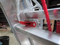
Figure 1. Example of Flipper-Lock
Flipper-lock occurs frequently when a user is adjusting the height of a ladder.
We have a prototype solution to this form of false locking:
Alternative Flylock Design
The flipper gate can be totally eliminated with the design shown in the following photographs. The totally redesigned flylock uses a member which pivots the flylock about each rung, allowing adjustment of the ladder height, with no possibility of flipper-lock occurring, because, there is no flipper!
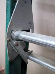
Figure 2. Generation 1 "Push-Off Design"
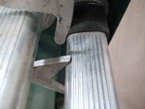
Figure 3. Generation 2 "Push-Off Design"
Tip-lock
Tip-lock occurs when the tip of a fly-lock rests on a ladder rung. This occurs often when the user puts downward force on the upper ladder section before the fly-lock can rotate to the proper locked position. This mode of false-locking can seem very secure but can become disengaged at any time.
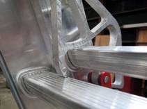
Figure 4. Example of tip-lock
Alternative Flylock Design
Safety Engineering Resources continued developing prototype flylocks. To overcome the danger of tip-lock, a roller was added to the end of the flylock tip. This makes it nearly impossible for the tip to become stuck on the ladder rung. In preliminary experimentation, this design eliminated tip-lock.
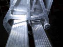
Figure 5. Prototype Roller on the Tip of the Flylock
End-Lock
End-lock occurs when the bottom of the side rail of the upper ladder section rests on a lower ladder rung and becomes false-locked. This produces a very dangerous false lock that can seem to be securely locked with the ladder extended, but can slip off with catastrophic effects at any time. The following photograph shows an example of this mode of false-locking.
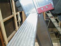
Figure 6. Example of end-lock
This will cause a false lock that is securely locked when the ladder is extended and the climber is in on the ladder. Access off the roof could easily dislodge the fly-section and the ladder would telescope downward.
We performed experiments to determine how easily extension ladders would end-lock. We discovered that it took only fifty pounds of force perpendicular to a fully extended ladder to cause the ladder to end-lock. When the ladder user was near the middle of the ladder, a quarter of an inch interference resulted, making it a very dangerous false-lock.
Universal Solutions
Our prototype experiments showed us that a fly-lock can be designed that will not false-lock under normal operating conditions. Another simple solution is to manually lock the two ladder sections together while the ladder is extended. This can be done a number of different ways. One variation was patented, a Ladder Safety Tip Strap, U.S. Patent # 5,896,945. This design utilizes a tie strap that locks the two sections together, making it impossible for the ladder to collapse.
Conclusion
Extension ladder accidents are usually due to the flylock of the ladder becoming false-locked. False-locked ladders are very unstable and can collapse at any moment, often with devastating results. Ladder manufacturers need to equip their ladders with a flylock mechanism that will not false-lock, and provide a means to manually lock the two ladder sections together.


